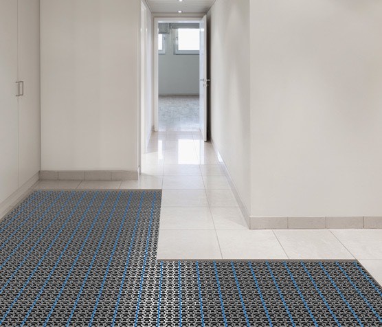
Tile is a natural for radiant heating.
However, installing tile with radiant heating can get overwhelming when you realize that the Tile Council of North America (TCNA) Handbook includes multiple methods that address this type of installation. The details vary somewhat depending on the structure you are working on and which type of heat source your radiant system uses - hydronic or electrical.
- On ground concrete
- Above ground concrete
- Wood subfloor/joist system
Fortunately, Mark Heinlein CTI #1112 and National Tile Contractors Association Training Director, Technical Trainer / Presenter shares his expertise in this article.
Hydronic or Electrical Radiant Heating?
In a hydronic system, pipes containing water or a heat transfer fluid are placed under the substrate, in the substrate, or on top of the substrate. The water or heat transfer fluid is warmed by a boiler and pumped through a system of valves and pipes. The heat from the pipes is transferred to the substrate and setting bed and tile and eventually into the ambient environment where it warms the space above the tile.
There are quite a few components to a hydronic heating system that will likely be designed by a mechanical engineer. The tile contractor can rely on the TCNA Handbook to guide the installation of tile on many of these systems.
In an electrical system, wires carry an electrical current beneath the tiles. These wires are very well insulated so the electricity does not create a safety hazard. The wires are designed to actually resist, or impede the flow of the electrical current. Heat is generated as electricity forces its way through the resistance of the wire. That heat becomes thermal energy that warms the substrate and setting bed and the tile. Depending on the electrical system, some of that heat will also warm the ambient environment in the space above the tile.
There are several varieties of electrical wire heating systems. Some come in preformed fiber mats that become integral with the setting bed. Some come attached to a mesh system that can be shaped and formed to fit the design of the room. Some come as a roll of special wire placed into the grid of a membrane that will become the underlayment for the tile installation.
This discussion will focus on installing electric radiant heat in a tile installation on an uncoupling membrane.

Electric Heating in an Uncoupling Membrane
The 2018 edition of the Tile Council of North America (TCNA) Handbook includes methods for installing uncoupling membranes for interior floors over concrete and wood substrates.
For your reference, these methods are F128, F147, and F148.
Many tile contractors and installers have become familiar with the process of installing uncoupling membranes in their tile system. Some manufacturers make versions of their membrane that allows for electrical heating wires to be applied onto the membrane before tile is installed. As with any tile-related installation product, installers must read and carefully follow manufacturer instructions for the installation of the heating wires (also known as elements) onto the membrane.
>> Do You Ignore Grout Manufacturer Directions?
Step 1: Unmodified vs. Modified Thinset Mortar: As Recommended by the Manufacturer
Before we get started installing the wire, let’s talk about the mortar we will use to install the membrane and the tiles onto the membrane after the wire is in.
It’s simple: Follow the manufacturer’s instructions and use the mortar they recommend for installing their product. Tile contractors and installers are smart. They know the difference between unmodified (ANSI A118.1) Dry-set Mortar and (ANSI A118.4) Modified Dry-set Mortar. And they know about the more highly modified (ANSI A118.11) EGP (Exterior Glue Plywood) Latex-Portland Cement Mortar and (ANSI A118.15) Improved Modified Dry-set Mortars.
With all our knowledge and information and experience, contractors and installers sometimes overlook the basic concept of following manufacturer’s instructions for the use of their specific products and combining these products into a system that carries a warranty.
I’ll say that again. System warranty.
This is an important thing to a cost-conscious installer and owner who is paying for an installation that s/he expects to last for a very long time.
I recommend what the TCNA Handbook recommends in the Materials section of Methods F128, F147, and F148 for installing uncoupling membranes that meet ANSI A118.12 standards. Here is what it says:
“Cementitious mortar – as recommended by the membrane manufacturer.”
The manufacturer will tell you in their installation instructions which type of mortar is recommended for using their membrane in your tile system. It’s a win-win. The tile contractor follows the TCNA Method and the manufacturer's requirements, then the system is protected by the manufacturer's warranty; the owner benefits from a great installation, the contractor gets paid, and everyone is happy.
Step 2: Does the Substrate Meet the Industry Standard for Flatness?
If you have ever been to one of my training workshops, you know that I sound like a broken record when it comes to substrate preparation. This is where it all begins. This is where a tile contractor/installer must examine the substrate BEFORE they begin tiling to ensure it meets the industry standard flatness requirement that you’ve read about on this site and in this blog.
>> See Is Your Floor or Wall Flat Enough for Large Format Tile?
I never get tired of quoting the standard requirements:
- 1/4” in 10’ for tiles with all sides less than 15” long
- 1/8” in 10’ for tiles with one side 15” or longer
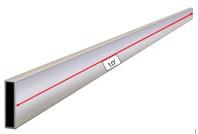
Check this with your 10’ straightedge. If you don’t own a 10’ straightedge, you need to purchase one. (No, I do not have stock in the 10’ straightedge company.)
>> See A Flat Floor vs. a Level Floor: What's the Difference?
If you find that the substrate that the uncoupling membrane will be installed on does not meet industry standards for flatness, then the contractor responsible for the substrate needs to make it flat. If that person is you, well then you need to make sure you get paid for making it flat.
To make the substrate flat, use one or more of these methods:
- Grind the high spots (be certain to follow OSHA requirements for silica dust containment)
- Fill the low spots with appropriate rapid-setting patch material
- Install a mortar bed
- Install a liquid primer and self-leveling underlayment
>> See The Ultimate Guide to Underlayment for Tile
In most circumstances, the most appropriate method for flattening the substrate before installing an uncoupling membrane is a combination of grinding the high spots and filling low spots with rapid-setting patch material.
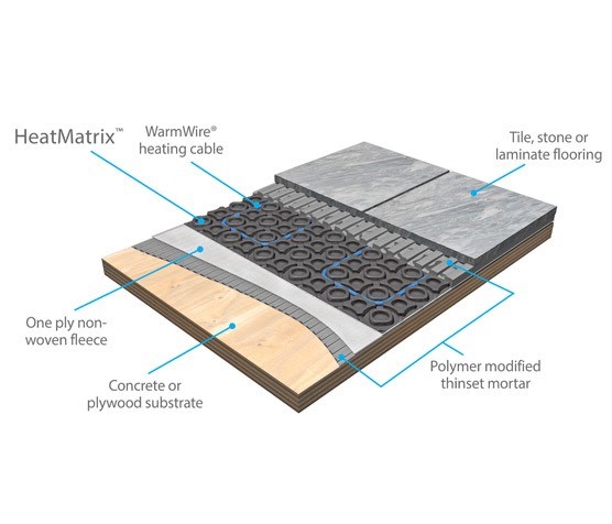
Step 3: Install the Membrane
The substrate is flat.
You’ve purchased the manufacturer-recommended mortar.
Now it’s time to install the membrane. But, before mixing up the mortar (using its manufacturer’s instructions) let’s talk about the perimeter of the room.
Are the perimeter movement joints clean and open?
Everyone knows that ANSI standards and the TCNA Handbook Method EJ-171 require a movement joint where the floor tile will meet a wall or where it will meet a cabinet or curb or column or pipe or… you get the idea. So, our tile can’t bump up tightly to these objects. Neither can our substrate.
For example, if we were using Cementitious Backer Unit (CBU) as our substrate, we would not want that CBU bumped up tightly at any point of the perimeter or change in plane. We would want a nice, open joint about ¼” wide consistently at the perimeter. We would not want any mortar or grout in that nice, clean open joint, because that would defeat the purpose. But we already know all that, right?
What I want to make sure we talk about is that we have to keep our uncoupling membrane a nice consistent ¼” away from any obstacle or change in plane and at all perimeters. The same way we do with CBU.
When we are installing the membrane and some mortar squeezes out from underneath and gets between the membrane and the lumber at the bottom plate of a wall, we need to clean it out. If we leave that mortar there to dry, it will create a hard joint and will defeat the purpose of allowing the installation and the structure to move.
Ok. So now we are ready to mix our mortar and install the membrane.
Did you eliminate bond breakers on the subfloor?
Wait. Nope. Did we check to make sure there are no bond breakers on the subfloor?
We don’t want to do all of this and then expect our system to be held together by the paint overspray that is on the plywood from the painter’s spray gun.
If that's the case, we're going to have to sand that paint off then clean up the subfloor and make sure there is no dust or dirt or sealer or any other material that will keep the mortar from properly adhering to the membrane to the subfloor.
Alright. Now mix up the mortar to the manufacturer’s instructions and install the membrane.
Step 4: Install the Heating Wire
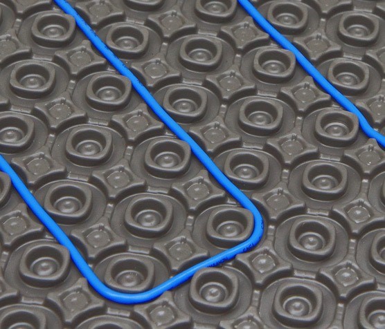
You’ve got the membrane down. Now it’s time to install the electric heating wire.
Every wire manufacturer has specific instructions describing how to place their wire in their uncoupling membrane system. For instance,
- They will tell you how far apart to place the rows of wire, how close to or how far from the wall the wire should be, etc.
- They tell you how to test the wire before you get it off the roll.
- Some require a couple of simple electrical checks.
- You need to know where the thermostat is or will be and if you have enough lead wire to get to it.
- You need to know where the temperature-sensing probe for the thermostat will be placed.
- You need to remember to install the temperature-sensing probe so the system works.
So now you wonder why the tile contractor is now an electrician? Look at it this way, it’s another tool in your toolbox to make money. You won’t be working with live electricity, but you do need to learn about the electrical wire system you are installing and you do need to have a plan before you begin. Just like every aspect of any tile installation.
I’m not going to tell you all the details of installing every manufacturer’s wire system but I am going to tell you this: Read and follow the manufacturer’s instructions.
- Call them up when you have questions.
- Make absolutely certain you have a complete understanding of how their system goes in BEFORE you begin.
- Get some specific hands-on training from the manufacturer. It will be well worth your time.
If you are an owner looking for an installation, interview a trained, seasoned, qualified professional tile contractor.
Step 5: Install the Tile
The wire is in. It’s been tested. The test results have been written down on the warranty card. Now you are ready to tile.
Not so fast… Here is another suggestion from me: Take pictures first. Pull out your phone or camera and take pictures of every section of the wire installation. Make sure you have a reference point in each photo so you can align them to the room after the tile is down and the grout is installed and everything is cured.
Make sure your pictures show:
- The location of the temperature-sensing probes
- The location of the thermostat lead wires and temperature sensing probe wires
- The spacing and distance of the wires from each other
- The distance of the wires from obstacles like walls and toilets and heat registers and vanities
- Any other pictures you think you need to document your wire installation
You will very likely NEVER have to look at these pictures again. Especially if you did everything correctly.
Double-check every detail of your installation.
Ok. Now install the tile and do a great job.
Step 6: Heed the Warranty Card
After the tile is installed test the wires once again. Make sure all of your readings are still correct. Make sure you record this on the warranty card. Make sure you fill out and give the owner the warranty card that came with the heating system. If the card has all those electrical readings that you wrote down, make a copy and keep it in your job file.
The owner of this installation is going to be so happy with it and with you for doing such a great job installing it. You’ll probably never hear from them again unless it is to hire you for more work. That’s just the way I like it.
.jpg?width=400&name=Horror-twenty20_38a8b249-f3a8-4f03-990f-695ed839a923%20(650x435).jpg)
Troubleshooting Electrical Radiant Heating
You are on to the next job. Your phone rings…
… It’s the owner of the job you installed the electrical heat system and it's not working. Now what?
For starters, you can verify the electrician was there to connect the leads to the thermostat and install it. You can verify the owner is using the thermostat correctly. You can verify with the electrician that s/he connected the temperature sensing probe you so carefully and accurately placed in the system.
If all that seems to be in order, all those pictures you took suddenly become very interesting to look at. Pore over them to make sure you didn’t miss any details. You didn’t accidentally place the probe where a rug was going. Or where the sun beats down on it all day. Make sure your wires are spaced properly.
Everything looks to be in order. Now what?
Well, these systems are really well built to withstand the tile installation process. So the chances are it didn’t fail on its own. Everything looks good in the pictures you took. Your electrical readings were all recorded and were within tolerance. But you can’t see the wire through the tile to see how it is performing or find where the problem is.
Wait, yes you can…
Common issues with electrical wire installations and how to find and fix them
There's a fairly common myth that if something happens with the electrical heat installation there are two alternatives.
- Live with it.
- Tear out the whole thing and redo it.
Not necessarily. There is at least one more alternative:
A trained, experienced electrical technician using the proper test equipment and testing techniques can diagnose the cause and pinpoint the location of the problem.
It’s almost like being able to see through the tile.
I know of several instances where tile contractors and owners saved thousands of dollars by contacting the manufacturer of the heating system who put them in touch with a trained, qualified, and properly equipped technician who could diagnose, locate and repair the problem, sometimes by removing only one or two tiles.
Sometimes it’s fairly simple. Sometimes not so much.
Common electrical radiant heating system issues
These are a few common issues with electrical heating systems.
- Heating system wires too close to walls or under the trim base
- Heating system wires under buildouts or appliances such as cabinets, vanities, bathtubs, etc.
- Cut cables – usually caused by a utility knife cleaning out joints between the tiles before grouting
- Screws or fasteners driven through heating cables. This is usually a result of a lack of communication between the tile contractor and the
- shower door installer,
- or the finish carpenter who installs a doorstop on the floor,
- or a plumber who installs a floor-fastened toilet,
- or ….
- Incorrect spacing between heating cables. Too close or too far apart.
A FLIR (Forward Looking InfraRed) Thermal Imaging Camera is often used to view the heat signature of the electrical wires beneath the tile.
Wires not installed correctly
Below is a photo of heating cables - identified by a FLIR camera - that were not installed according to manufacturer instructions.
- In one area, the wires were installed too far apart to properly interact with each other and they didn’t create heat. That's the deep pink/purple section on the left of the photo.
- In the adjacent area, the wires were installed too close together, creating too much heat. That's the bright yellow section toward the middle of the photo. The result was a vastly uneven heat in the floor.
Had it been used much more, the whole system would have failed, requiring the owner to just suck it up and live with it, or have the tile contractor do a full tearout and replacement. Can you guess which happened?

The subfloor wasn't flattened before installing radiant heating
Here is a story of an easier repair but a not-so-bright move by a tile installer who didn’t flatten the subfloor before installing the uncoupling membrane.
There were some humps and dips in the subfloor. The uncoupling membrane was installed on top of the humpy, dippy subfloor. Those humps and dips translated right up through to the top of the membrane after it was installed. No worries thought the installer, “I’ll just add or take away thinset as I usually do when I set tile.” (This is another subject you can get me wound up about, just not today).
>> See Have You Adequately Prepped the Substrate for Tile?
So that’s what he did. Except, when he got to the transition between the tile and the wood flooring in the next room. There was a hump in the floor right at the transition that the installer didn’t find until he worked his way setting tile out the door. Now what? Well, out comes a nice sharp utility knife to cut away the uncoupling membrane and bring the bottom of the tile down to the top of the wood subfloor (with very little mortar bond coat beneath it). Problem solved.
The installation looks good and everything is ok until the heat is turned on a couple of weeks later and the floor doesn’t get warm. What happened? You guessed it. After much stress and muss and fuss and calling in the heating system manufacturer the sliced wire was found at the entrance where the installer cut out the membrane to get the finished height to match the wood.
This is a case when a qualified repair technician was able to locate the failure and ultimately save the day when only one tile had to be removed to repair the sliced cable.
Here is a picture of that repair. You’ll note as I did, there are still a bunch of probable failures waiting to happen with this job. At least the wire could be repaired.
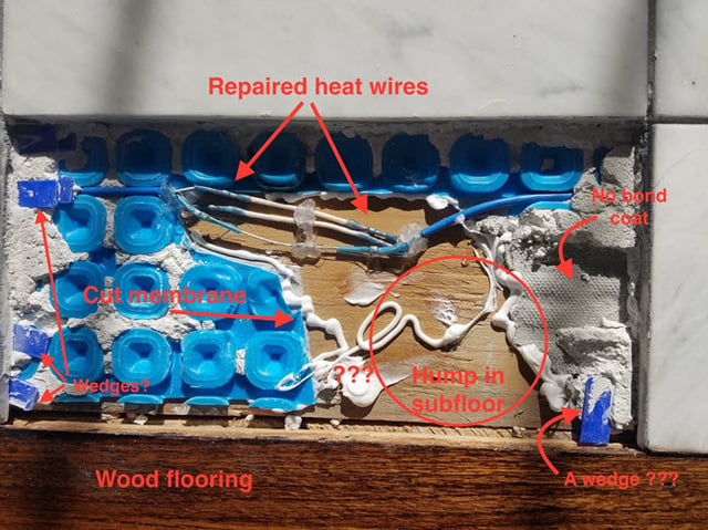
Please Note: None of the products shown in this photo led to the failure we see. The failure and other issues were a result of not following several tile industry standards and best practices or product manufacturer instructions.
Radiant Heating Installation Successes
It can be instructive to look at failures. But there are a giant number of electrical radiant heat system installations with uncoupling membranes under tile happening every day. These are created by the very many tile installers and contractors who know how to read and follow manufacturer instructions.
They also own and use the tile industry standards published in ANSI A108 and the methods and best practices published in the Tile Council of North America (TCNA) Handbook.
I hope this helps you understand a bit about these installations and how to make certain every tile installation is a great one.
Thanks for reading!
Mark Heinlein - CTI #1112
Special thanks to SunTouch - A Watts Brand for contributing technical information and support for this article.
Note: We originally published this article on 12/04/2018, and have updated it.

